- 您现在的位置:买卖IC网 > Sheet目录62 > MLX90215EVA-AAA-106-BU (Melexis Technologies NV)IC SENSOR PROG LINEAR HALL 4SIP
Activation - Using Hall-Effect Switches
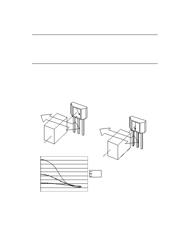
A switch requires a Hall IC, a magnet and a means of moving the magnet or the magnetic field. Figures 2, 3
and 4 show several ways by which a magnet can control the Hall IC switch. The following examples are simi-
lar in principle to most real applications. Slide-by, proximity and interrupt configurations represent the three
basic mechanical configurations for moving the magnet in relation to the Hall IC.
Slide-by Switch
In the Slide-by configuration, the motion of the magnet changes the field from North to South within a small
range of motion. This configuration provides a well defined position and switching relationship. The minimum
required motion may be as little as 1 or 2 mm.
Figure 2, Slide-by Switch
In Figure 2A, the South magnetic pole is too far away, so the switch stays OFF. In Figure 2B, the South
magnetic pole turns the switch ON.
Section 3 - Applications
3-3
S
N
A-03
Figure 2A
Linear Slide-By
-100
0
100
200
300
400
500
600
700
800
0
50
100
150
200
250
300
350
Distance in mils (thousandths of an inch)
.050" Airgap
.125" Airgap
.250" airgap
c
S
N
A-04
Figure 2B
Linear Slide-By, Alnico8
发布紧急采购,3分钟左右您将得到回复。
相关PDF资料
MX887DHTTR
MICROPOWER HALL-EFFECT SWITCH
MX887PHTTR
IC HALL EFFECT SW UPWR TSOT23-3
OMH3040S
SENSOR HALLOGIC HALL EFFECT
OPB122B
SWITCH SLOTTED OPTIC PHOTOLOGIC
OPB200
SENSR OPTO SLOT 5.1MM TRANS THRU
OPB202
SWITCH SLOTTED OPTICAL
OPB483T11
SWITCH PHOTOLOGIC SLOTTD OPTICAL
OPB660N
SENS OPTO SLOT 3.18MM TRAS W/RES
相关代理商/技术参数
MLX90215LVA
制造商:未知厂家 制造商全称:未知厂家 功能描述:Precision Programmable Linear Hall Effect Sensor
MLX90215LVA-AAA-111-BA
制造商:Melexis Semiconductors 功能描述:IC HALL EFFECT SENSOR PREC 4SIP
MLX90215LVA-AAA-111-BU
功能描述:IC SENSOR PROG LINEAR HALL 4SIP RoHS:是 类别:传感器,转换器 >> 磁性 - 霍尔效应,数字式开关,线性,罗盘 (IC) 系列:- 标准包装:1 系列:- 传感范围:20mT ~ 80mT 类型:旋转 电源电压:4.5 V ~ 5.5 V 电流 - 电源:15mA 电流 - 输出(最大):- 输出类型:数字式,PWM,8.5 位串行 特点:可编程 工作温度:-40°C ~ 150°C 封装/外壳:20-SSOP(0.209",5.30mm 宽) 供应商设备封装:20-SSOP 包装:Digi-Reel® 其它名称:AS5132-HSST-500DKR
MLX90215LVA-BC03
功能描述:IC SENSOR LIN HALL 10MV/MT 2.5V RoHS:是 类别:传感器,转换器 >> 磁性 - 霍尔效应,数字式开关,线性,罗盘 (IC) 系列:- 标准包装:1 系列:- 传感范围:20mT ~ 80mT 类型:旋转 电源电压:4.5 V ~ 5.5 V 电流 - 电源:15mA 电流 - 输出(最大):- 输出类型:数字式,PWM,8.5 位串行 特点:可编程 工作温度:-40°C ~ 150°C 封装/外壳:20-SSOP(0.209",5.30mm 宽) 供应商设备封装:20-SSOP 包装:Digi-Reel® 其它名称:AS5132-HSST-500DKR
MLX90215LVA-CC03
功能描述:IC SENSOR LIN HALL 20MV/MT 2.5V RoHS:否 类别:传感器,转换器 >> 磁性 - 霍尔效应,数字式开关,线性,罗盘 (IC) 系列:- 标准包装:1 系列:- 传感范围:20mT ~ 80mT 类型:旋转 电源电压:4.5 V ~ 5.5 V 电流 - 电源:15mA 电流 - 输出(最大):- 输出类型:数字式,PWM,8.5 位串行 特点:可编程 工作温度:-40°C ~ 150°C 封装/外壳:20-SSOP(0.209",5.30mm 宽) 供应商设备封装:20-SSOP 包装:Digi-Reel® 其它名称:AS5132-HSST-500DKR
MLX90215LVA-GC03
功能描述:IC SENSOR LIN HALL 50MV/MT 2.5V RoHS:否 类别:传感器,转换器 >> 磁性 - 霍尔效应,数字式开关,线性,罗盘 (IC) 系列:- 标准包装:1 系列:- 传感范围:20mT ~ 80mT 类型:旋转 电源电压:4.5 V ~ 5.5 V 电流 - 电源:15mA 电流 - 输出(最大):- 输出类型:数字式,PWM,8.5 位串行 特点:可编程 工作温度:-40°C ~ 150°C 封装/外壳:20-SSOP(0.209",5.30mm 宽) 供应商设备封装:20-SSOP 包装:Digi-Reel® 其它名称:AS5132-HSST-500DKR
MLX90215LVA-LA03
功能描述:IC SENSOR LIN HALL 100MV/MT 1V RoHS:否 类别:传感器,转换器 >> 磁性 - 霍尔效应,数字式开关,线性,罗盘 (IC) 系列:- 标准包装:1 系列:- 传感范围:20mT ~ 80mT 类型:旋转 电源电压:4.5 V ~ 5.5 V 电流 - 电源:15mA 电流 - 输出(最大):- 输出类型:数字式,PWM,8.5 位串行 特点:可编程 工作温度:-40°C ~ 150°C 封装/外壳:20-SSOP(0.209",5.30mm 宽) 供应商设备封装:20-SSOP 包装:Digi-Reel® 其它名称:AS5132-HSST-500DKR
MLX90215LVA-LC03
功能描述:IC SENSOR LIN HALL 100MV/MT 2.5V RoHS:否 类别:传感器,转换器 >> 磁性 - 霍尔效应,数字式开关,线性,罗盘 (IC) 系列:- 标准包装:1 系列:- 传感范围:20mT ~ 80mT 类型:旋转 电源电压:4.5 V ~ 5.5 V 电流 - 电源:15mA 电流 - 输出(最大):- 输出类型:数字式,PWM,8.5 位串行 特点:可编程 工作温度:-40°C ~ 150°C 封装/外壳:20-SSOP(0.209",5.30mm 宽) 供应商设备封装:20-SSOP 包装:Digi-Reel® 其它名称:AS5132-HSST-500DKR